Ordering custom roll labels without locking the unwind direction code, core diameter, sensor gap pitch, and liner release window causes inverted bottle copy, missed photoelectric triggers, or snapped webs that create line downtime and rework on the labeling machine. Specify the complete roll-to-machine mechanical interface before the converter cuts dies or slits finished reels.
An automatic label machine requires five synchronized roll specifications: copy unwind position (#1 through #8), core inner diameter and maximum outer roll diameter (typically a 3.0 inch / 76.2 mm core and 12.0 inch / 304.8 mm maximum OD on inline unwinders), die-cut repeat pitch with a minimum 1/8 inch (3.175 mm) inter-label gap and 1/16 inch (1.588 mm) side liner margins, sensor detection contrast (opacity step or printed black eye-mark), and release liner tensile and high-speed release stability under FINAT FTM 4 (10 to 300 m/min).
| Mechanical parameter | Standard industrial specification | Primary failure mode if mismatched | Engineering verification step |
|---|---|---|---|
| Copy unwind direction | Chart Positions #1 to #4 (wound out) or #5 to #8 (wound in); #3 and #4 standard for side/wrap heads | Artwork applies upside down or backward on the container wall | Trace web threading from unwind spindle to peel beak against container travel direction |
| Core inner diameter (ID) | 3.0 in (76.2 mm) fiberboard or plastic core (+0.00 / +1.5 mm mandrel clearance) | Reel cannot mount on expanding spindle, or 1 in core induces severe inner-wrap label curl | Match core ID and wall thickness (3.2 to 6.4 mm) to unwinder mandrel specification |
| Maximum roll outer diameter (OD) | 8.0 in (203.2 mm) inside printer housings; 12.0 in (304.8 mm) to 16.0 in (406.4 mm) on open unwinders | Over-sized roll rubs machine frame or exceeds unwind brake torque during indexing | Measure clear swing radius and brake inertia limit on the applicator stand |
| Inter-label gap and edge trim | 1/8 in (3.175 mm) web-direction gap; 1/16 in (1.588 mm) exposed liner per side | Fork sensor misses stop edge (double feed) or adhesive ooze fouls guide rollers | Verify die layout repeat length and cross-web liner width before press tooling approval |
| Clear-label sensor contrast | Opaque black registration mark (3.2 to 4.8 mm high) on liner back, or ultrasonic fork sensor | Photoelectric optical sensor sees zero contrast through clear BOPP/PET on clear PET liner | Specify back-printed eye-mark aligned to leading edge or confirm ultrasonic/capacitive head |
| Release liner & kiss-cut depth | BG40 glassine (50 to 57 micrometers) or PET23/PET30 (23 to 30 micrometers); die score <= 10% to 15% of liner | Deep die strike breaches silicone barrier and snaps web over the 180-degree peel plate | Audit FTM 3 / FTM 4 release force (10 to 30 cN/25 mm) and check stained liner for die bruising |
Unwind direction chart #1 to #8: matching copy position to applicator hand
Every automatic labeling machine feeds the pressure-sensitive web along a fixed roller path from the unwind mandrel to the dispensing peel plate (beak). Because the roll can only mount on the spindle in one axial orientation while keeping the liner side against the peel plate, the converter must wind the finished roll so the correct edge of the artwork crosses the beak first. North American and international converters standardize this orientation using the eight-position unwind chart documented by PennPac, Labeltronix, and Blue Label Packaging.
Positions #1 through #4 are wound out (labels sit on the outside surface of the roll, facing away from the core). Positions #5 through #8 are wound in (labels sit on the inside surface of the roll, facing toward the core so the exposed liner forms the outer wrap). Within each group of four, the number designates which edge of the upright text or graphic leads off the roll as the web unwinds:
| Unwind code | Winding side | Leading edge off roll | Copy reading axis relative to web | Standard labeling machine configuration |
|---|---|---|---|---|
| Position #1 | Wound out (labels outside) | Top edge leads | Across the web (transverse) | Top-apply tamp-blow or overhead wipe-on heads feeding in line with container travel |
| Position #2 | Wound out (labels outside) | Bottom edge leads | Across the web (transverse) | Under-conveyor bottom labelers or reversed overhead wipe-on applicators |
| Position #3 | Wound out (labels outside) | Right edge leads | With the web (parallel) | Right-hand side-wipe, wrap-around belt, and rotary stations (containers moving left-to-right) |
| Position #4 | Wound out (labels outside) | Left edge leads | With the web (parallel) | Left-hand side-wipe, opposed second head on front-and-back systems, or right-to-left lines |
| Position #5 | Wound in (labels inside) | Top edge leads | Across the web (transverse) | Serpentine top applicators and print-and-apply units that invert the web over an idler roller |
| Position #6 | Wound in (labels inside) | Bottom edge leads | Across the web (transverse) | Serpentine bottom applicators with internal web-turn rollers |
| Position #7 | Wound in (labels inside) | Right edge leads | With the web (parallel) | Inside-wound right-hand side applicators where roller geometry flips the web before the beak |
| Position #8 | Wound in (labels inside) | Left edge leads | With the web (parallel) | Inside-wound left-hand side applicators and specialized rotary pharmaceutical heads |
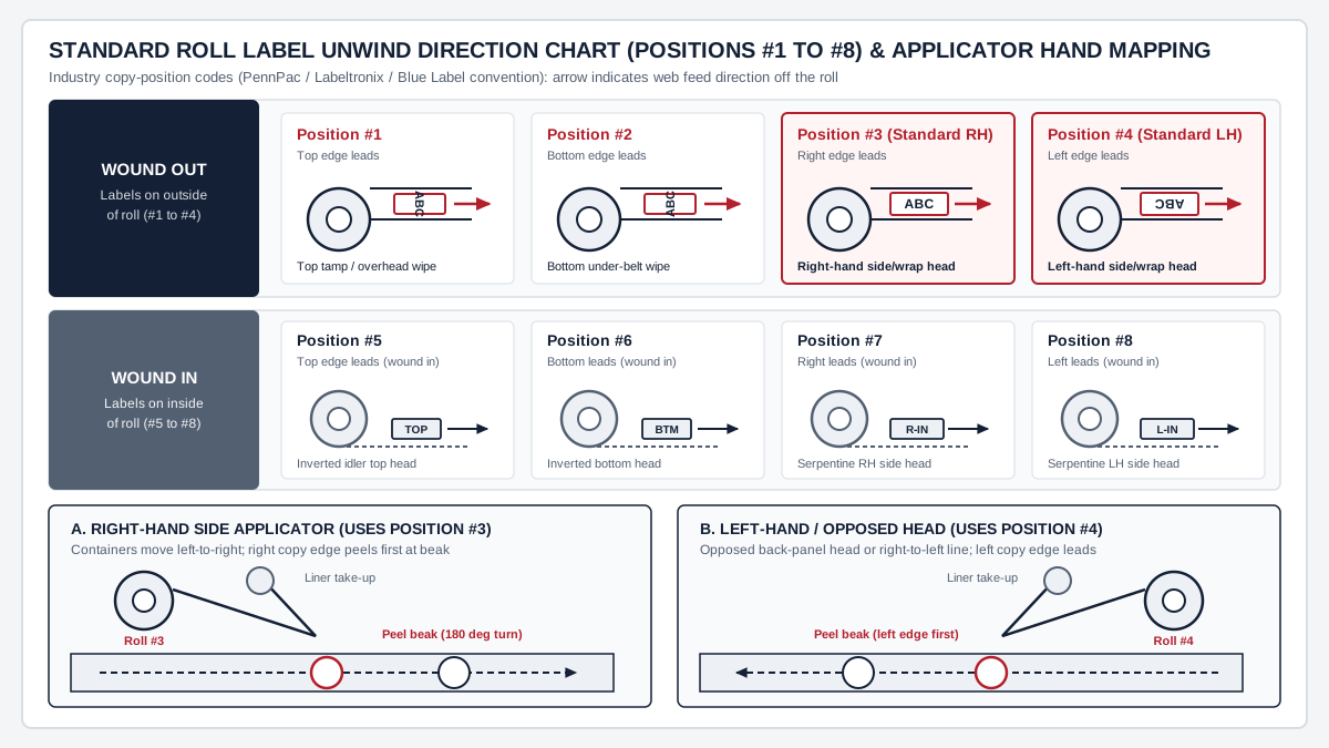
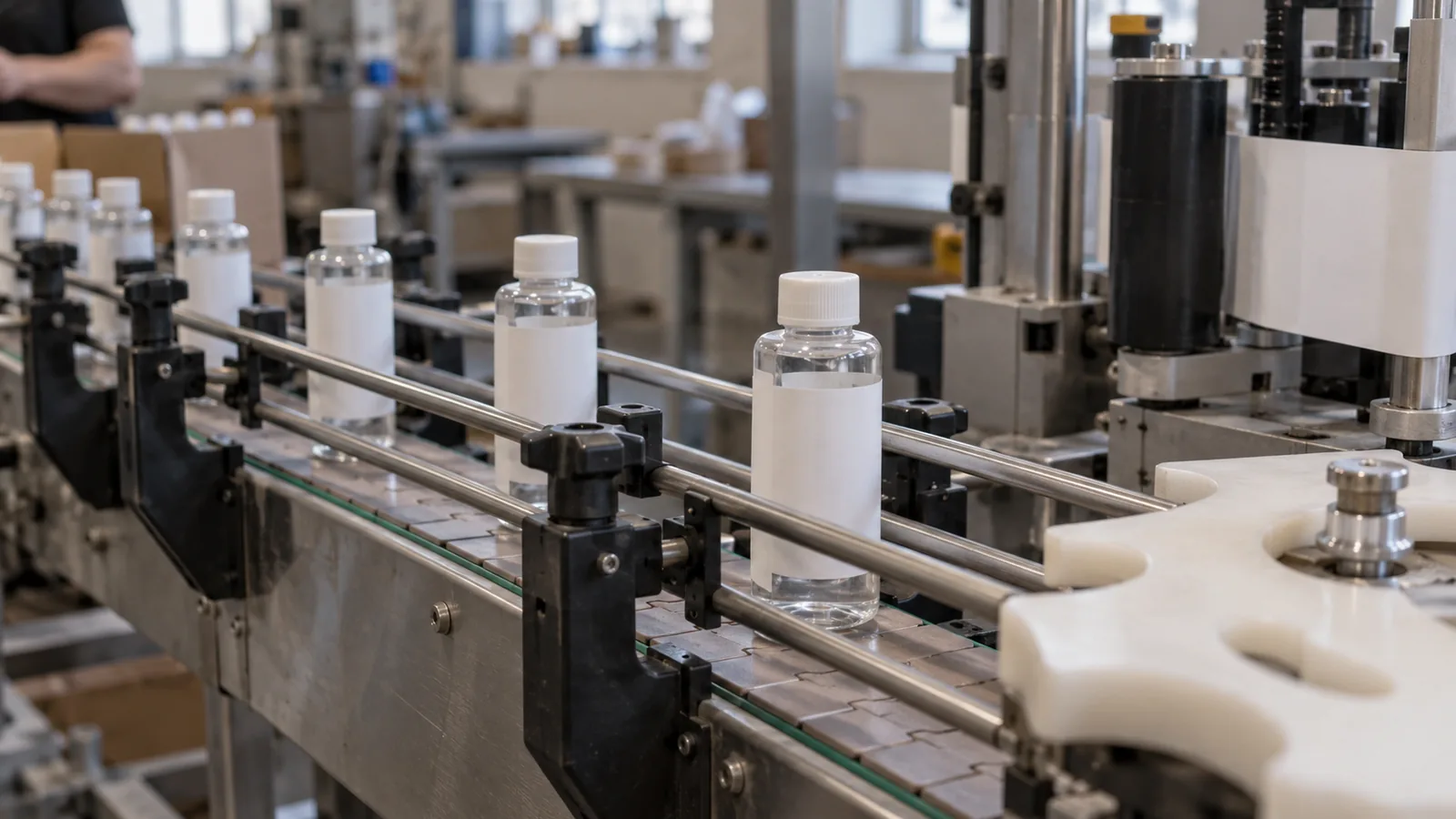
On vertical bottle lines, Positions #3 and #4 account for the vast majority of custom roll labels. When a bottle travels left-to-right past an operator standing in front of a side-wipe or wrap-around station, the dispensing beak points toward the approaching bottle’s right flank. For upright text to land right-side-up on the container wall, the right edge of the copy must peel off the liner first, which requires Position #3. On a dual-head front-and-back inline labeler where two applicator heads sit on opposite sides of the conveyor, one head operates as a right-hand unit (Position #3) while the opposed head operates as a left-hand unit (Position #4).
Rule of thumb: If a front-and-back bottle line uses two opposed side-wipe applicator heads straddling a straight conveyor, specify Position #3 for the right-hand head and Position #4 for the left-hand head. Ordering both front and back rolls in Position #3 forces one label to apply upside down unless the machine includes an inverting idler-roller kit.
Keep the roll unwind code paired with the container orientation record defined in the inline versus rotary container requirements guide and the broader labeling equipment section.
Takeaway: Lock the unwind code (#1 to #8) against the exact applicator head hand and roller threading diagram before approving pre-press proofs.
Core inner diameter, maximum roll OD, and labels-per-roll math
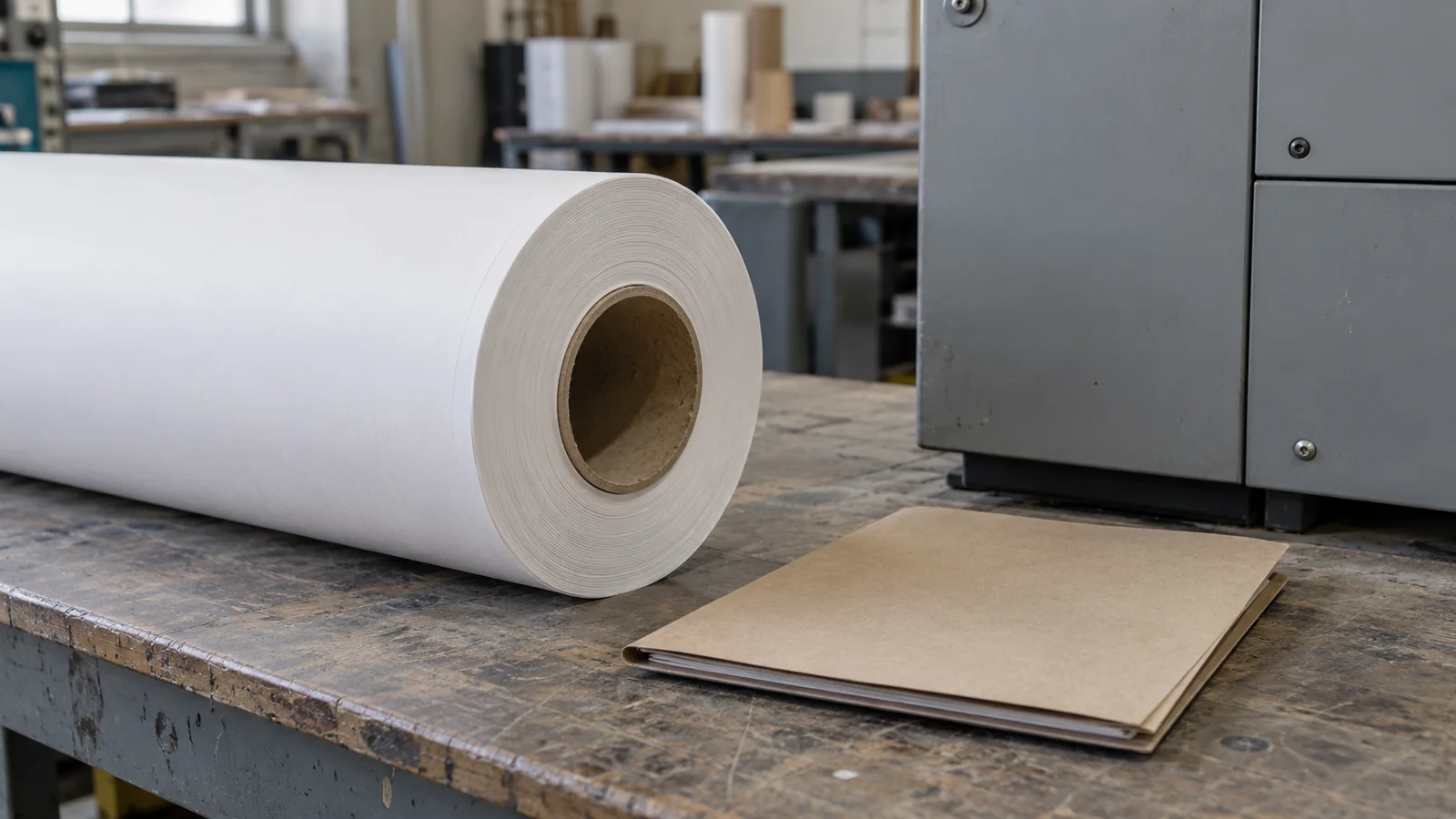
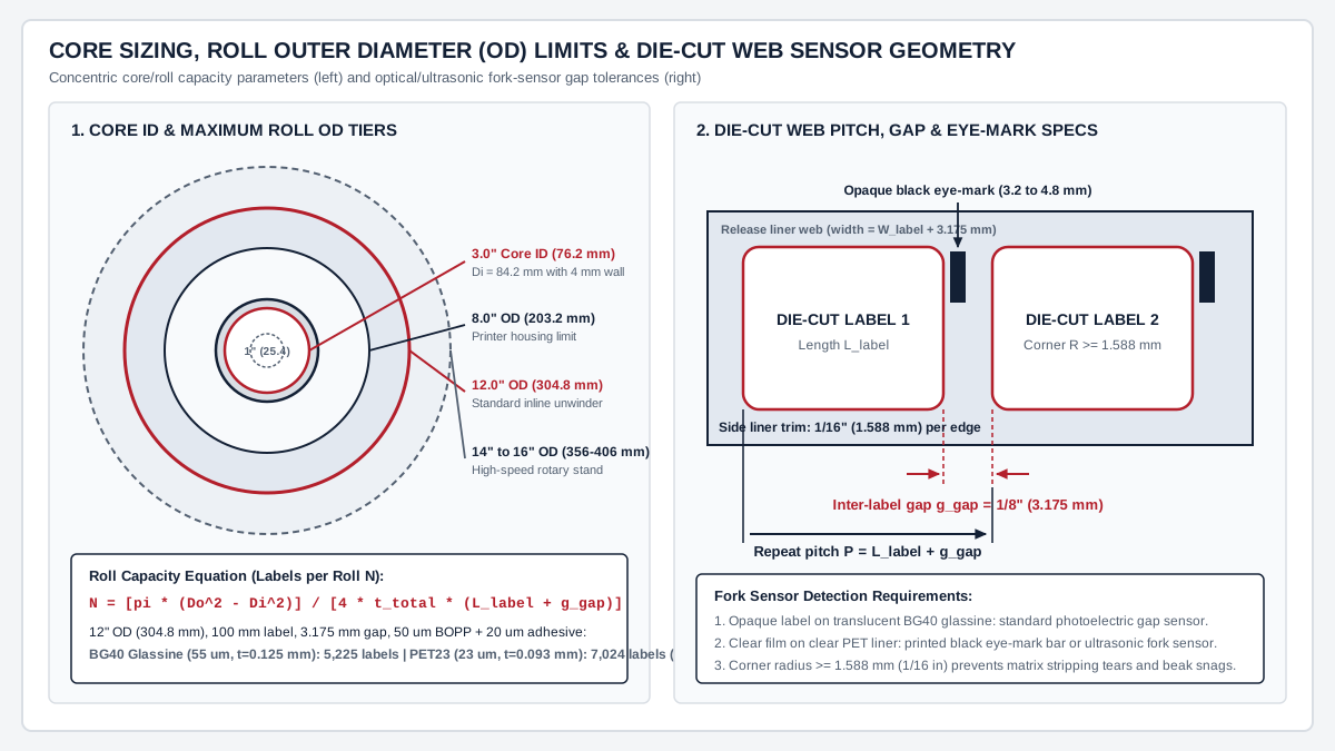
The roll core inner diameter (ID) and maximum outer diameter (OD) govern both physical mounting on the unwinder spindle and the rotational inertia that the unwind brake must arrest between labels. As detailed in Labeltronix’s machine specification guide, industrial labeling machines standardize on a 3.0 inch (76.2 mm) core ID, whereas desktop thermal printers and high-speed rotary beverage turrets occupy smaller and larger tiers.
| Equipment tier | Standard core ID | Core wall thickness | Maximum roll OD limit | Mechanical and web-handling constraint |
|---|---|---|---|---|
| Desktop thermal printers & bench dispensers | 1.0 in (25.4 mm) or 1.5 in (38.1 mm) | 2.0 to 3.2 mm (0.080 to 0.125 in) kraft paperboard | 4.0 to 5.0 in (101.6 to 127.0 mm) | Tight 25.4 mm radius imparts high curl memory to stiff films (>= 50 micrometers), causing pre-dispensing near the core |
| Industrial print-and-apply & inline labelers | 3.0 in (76.2 mm), tolerance +0.0 / +1.5 mm | 3.2 to 6.4 mm (0.125 to 0.250 in) spiral kraft | 8.0 in (203.2 mm) internal housing; 12.0 in (304.8 mm) open unwinder | Universal expanding-mandrel fit; keeps roll mass at 4 to 10 kg so start-stop indexing does not snap the web |
| High-speed continuous inline & rotary beverage stations | 3.0 in (76.2 mm) or 6.0 in (152.4 mm) | 6.4 to 9.5 mm (0.250 to 0.375 in) reinforced fiber or ABS | 14.0 to 16.0 in (355.6 to 406.4 mm); up to 19.7 in (500 mm) on servo stands | Eliminates tight inner-wrap curvature and extends roll run time beyond 30 to 60 minutes at 400 to 800 bottles/min |
For any given core and outer diameter limit, the total web length L_web (in millimeters) and the number of labels per roll N follow the spiral annulus area equation:
L_web = [pi * (D_o^2 - D_i^2)] / (4 * t_total)
N = L_web / (L_label + g_gap) = [pi * (D_o^2 - D_i^2)] / [4 * t_total * (L_label + g_gap)]
In these equations, D_o is the finished roll outer diameter (mm), D_i is the outer diameter of the core tube including its wall thickness (Core ID + 2 * t_wall, in mm), t_total is the combined caliper of one wrap (t_face + t_adhesive + t_liner, in mm), L_label is the label dimension along the machine feed direction (mm), and g_gap is the inter-label matrix gap (mm).
Worked calculation example (BG40 glassine paper liner vs PET23 film liner on a 12-inch OD roll):
Consider an inline labeling machine with a 12.0 inch (D_o = 304.8 mm) maximum roll OD limit running on a 3.0 inch core (76.2 mm ID with a 4.0 mm fiberboard wall, where D_i = 84.2 mm). The bottle label measures L_label = 100.0 mm in the feed direction with a standard 1/8 inch gap (g_gap = 3.175 mm), which sets a repeat pitch of P = 103.175 mm. Both candidate constructions use a 50 micrometer (0.050 mm) BOPP facestock and a 20 micrometer (0.020 mm) permanent acrylic adhesive:
- Construction A (55 micrometer BG40 glassine liner): Total wrap caliper is
t_total = 0.050 + 0.020 + 0.055 = 0.125 mm. Substituting into the web length formula yieldsL_web = [3.1416 * (304.8^2 - 84.2^2)] / (4 * 0.125) = [3.1416 * (92,903.04 - 7,089.64)] / 0.500 = 539,182 mm(539.2 meters). Dividing by the103.175 mmpitch givesN = 539,182 / 103.175 = 5,225 labels per roll. - Construction B (23 micrometer PET23 polyester film liner): Total wrap caliper drops to
t_total = 0.050 + 0.020 + 0.023 = 0.093 mm. At the exact same304.8 mmouter diameter limit, web length increases toL_web = [3.1416 * 85,813.40] / (4 * 0.093) = 724,707 mm(724.7 meters), yieldingN = 724,707 / 103.175 = 7,024 labels per roll.
Switching from a 55 micrometer glassine liner to a 23 micrometer PET liner packs 34.4% more labels (+1,799 labels) onto the same 12.0 inch OD reel. That matches the 15% to 35% roll-capacity gain reported by Packaging Strategies and UPM Raflatac, directly cutting unwinder roll-changeover stops on high-speed lines. The exact label count on a production reel varies with wound web tension, adhesive coat-weight tolerance, and ink or varnish build.
Takeaway: Size core ID and roll OD to the unwinder spindle and brake envelope first, then use total construction caliper t_total to calculate exact labels per reel.
Sensor gap pitch, edge trim, corner radius, and clear-label eye marks
Automatic labelers index each label by detecting the physical or optical transition between the trailing edge of one label and the leading edge of the next as the web passes through a fork sensor upstream of the peel beak. As documented by E-PAK Machinery and Labeltronix, reliable indexing and waste-matrix stripping depend on four die-cut web geometry rules:
| Web geometry feature | Standard engineering value | Converting and applicator mechanism |
|---|---|---|
Inter-label gap (g_gap, machine direction) |
1/8 in (0.125 in / 3.175 mm) standard; 3/16 in (4.76 mm) for thick multi-ply booklets | Gives the fork sensor a distinct translucent or caliper window to fire the servo/stepper brake stop |
| Liner side margin (cross-web edge trim) | 1/16 in (0.0625 in / 1.588 mm) per side minimum (liner width = W_label + 3.175 mm) |
Keeps the continuous waste skeleton intact during press stripping and stops edge adhesive ooze from gumming sensor guides |
Die-cut corner radius (R) |
>= 1/16 in (1.588 mm) on standard panels; >= 1/32 in (0.8 mm) on miniature vials | Prevents 90-degree stress-concentration tears in the waste matrix and initiates smooth delamination across the peel beak |
| Clear-on-clear registration mark (eye-mark) | Opaque black printed bar on liner underside: 1/8 to 3/16 in (3.2 to 4.8 mm) high by >= 3/8 in (9.5 mm) wide | Creates an optical trigger when transparent film labels on clear PET liners provide zero light-transmission contrast |
When a project specifies a transparent BOPP or PET facestock for a no-label look (compare the optical proof steps in the clear versus white bottle labels guide), a standard photoelectric gap sensor cannot distinguish the clear label from a clear PET release liner. The packaging engineer and converter must lock one of two hardware-compatible options before printing:
- Print a solid, non-reflective black registration eye-mark on the back of the release liner aligned to the leading edge of each label so an optical reflection or transmission sensor can trigger cleanly.
- Equip the labeling head with an ultrasonic or capacitive fork sensor that reads the
50 to 70 micrometerthickness step (t_face + t_adhesive) across the3.175 mmgap without relying on light opacity.
On small-diameter containers where short panels and tight radii govern edge lift, pair these die-cut corner radius and gap tolerances with the small cosmetic bottle and jar label zone guide and the booklet and extended content labels (ECL) engineering guide.
Takeaway: Maintain a 3.175 mm (1/8 in) inter-label gap, 1.588 mm (1/16 in) side liner margins, and >= 1.5 mm corner radii, and specify either a back-side black eye-mark or an ultrasonic sensor for clear-on-clear rolls.
Glassine vs PET release liners, FINAT FTM 3/4 release force, and kiss-cut depth
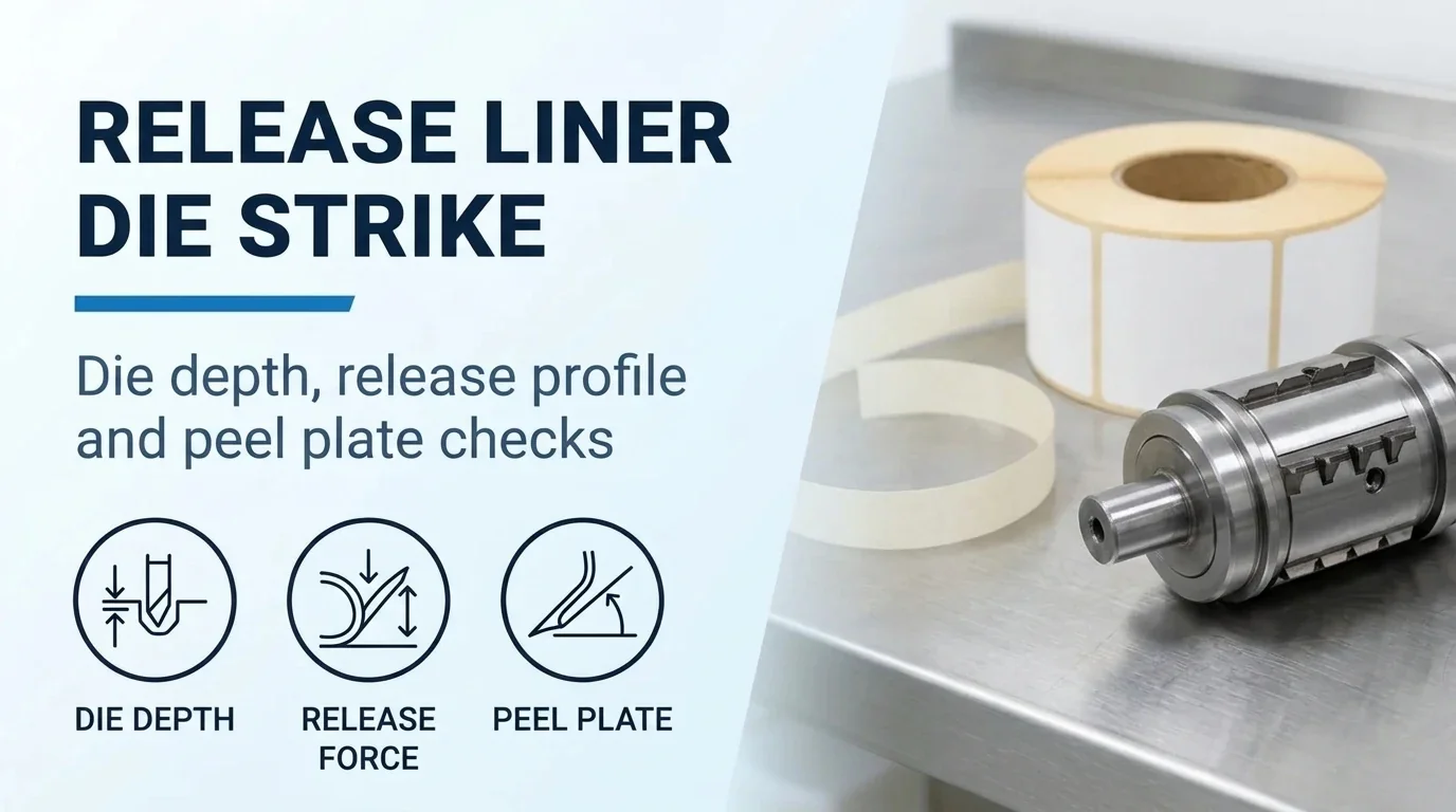
In the three-layer pressure-sensitive construction record, the release liner is not passive packaging waste; it is the load-bearing conveyor belt that pulls the die-cut labels through the applicator under unwind brake tension and bends nearly 180 degrees around a sharp 1.5 to 3.0 mm radius peel beak. Avery Dennison and UPM Raflatac divide industrial roll liners into two primary material classes: supercalendered glassine paper (such as BG40 / 40# SCK) and biaxially oriented polyester film (PET23 and PET30).
| Engineering property | Supercalendered glassine paper (BG40 / 40# SCK) | Polyester film liner (PET23 / PET30) | Impact on converting press and labeling machine |
|---|---|---|---|
| Basis weight (ISO 536) & nominal caliper (ISO 534) | 58 to 65 g/m2; 50 to 57 micrometers (2.0 to 2.25 mil) | 32 to 42 g/m2; 23 to 30 micrometers (0.92 to 1.2 mil) | Thin PET caliper yields 20% to 35% more labels per roll within the same OD limit |
| Caliper tolerance across web | Typically +-5% to +-8% fiber variation | Typically <= +-2% to +-3% extruded film uniformity | Flat PET anvil plane prevents alternating shallow and deep rotary die strikes across multi-lane tools |
| High-speed release profile (FINAT FTM 3 & FTM 4) | FTM 3 (0.3 m/min) and FTM 4 (10 to 300 m/min) release force rises with peel velocity and humidity swings | Flat, velocity-stable FTM 4 release curve across 10 to 300 m/min | Prevents speed-induced release lock-up when rotary turrets ramp from jog to full production speed |
| Wet-hall moisture & tensile behavior | Hygroscopic cellulose absorbs ambient water, causing edge curl and reduced wet tensile strength | Hydrophobic polyester retains full tensile break strength in wet or condensing beverage halls | Eliminates sudden liner snapping when washdown spray or bottle condensation contacts the web |
| Kiss-cut die penetration tolerance | Blade must cut face + adhesive while bruising <= 10% to 15% of glassine caliper (<= 5 to 8 micrometers) | Requires flexible rotary dies on hardened magnetic cylinders; score > 2 to 3 micrometers propagates a notch tear | Over-striking either liner breaches the ~1 micrometer silicone coating, causing adhesive lock-up and web breaks |
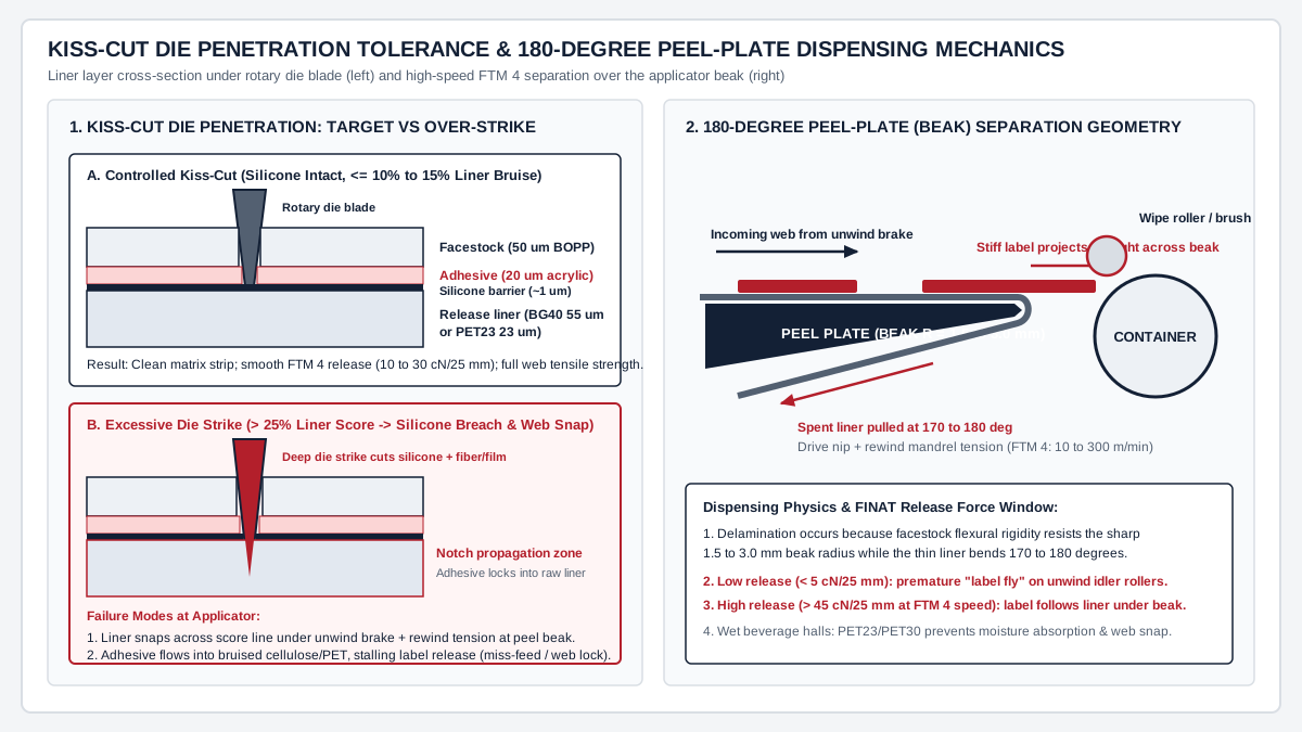
FINAT Test Methods govern how converters qualify liner delamination before reels reach the packaging line. FTM 3 measures low-speed release force at a 180-degree peel angle and 300 mm/min (0.3 m/min) jaw separation, whereas FTM 4 measures high-speed release force between 10 and 300 m/min, matching the real web speed of rotary converting presses and high-speed bottle applicators.
Rule of thumb: If high-speed FTM 4 release force falls below
5 cN/25 mm, stiff film labels (such as 50 micrometer BOPP or 50 micrometer PET; see the BOPP, PET, and PE bottle label comparison) prematurely pop off the liner around unwind idler rollers (“label fly”). If FTM 4 release force exceeds40 to 50 cN/25 mmor spikes because a deep rotary die strike fractured the silicone barrier, the label refuses to release at the peel beak, travels under the plate with the spent liner, or snaps the web under rewind nip tension.
Not every pressure-sensitive construction can run on an automatic peel-plate dispenser. Fragile security films such as destructible cast vinyl (for example, Avery Dennison spec 41100 documented in the tamper-evident VOID and destructible vinyl guide) have lower internal tear strength than the adhesive’s release force at a sharp beak and are restricted to manual application. Similarly, as CTM Labeling Systems notes, storing custom roll labels on high warehouse racks (where air temperatures run more than 20 degrees warmer than floor level) or leaving reels unsealed in humid rooms accelerates adhesive bleed into the die-cut gap, causing web breaks and post-application defects that must be isolated from container-surface issues in the filling and capping to labeling handoff and the bottle label bubbles, wrinkles, and lifting diagnostic guide.
Takeaway: Specify BG40 glassine for general dry lines and PET23/PET30 for wet beverage halls, clear-on-clear proofs, or high-speed rotary turrets, and enforce kiss-cut penetration within 10% to 15% of liner caliper.
Roll specification checklist for converter and machine sign-off
Before releasing a purchase order for custom roll labels or scheduling a line qualification trial, record the converter’s die-line parameters and the applicator’s mechanical limits on one shared specification sheet. Pair this mechanical roll record with the materials category guides for facestock/adhesive selection and the printing and application guides for artwork proof checks.
| Specification field | Target entry to lock on PO and proof | Verification method at incoming QC |
|---|---|---|
| Applicator head & unwind code | Specify machine model, right-hand vs left-hand mount, and Chart Position (#1 to #8) | Unroll first 500 mm by hand and verify leading copy edge matches approved proof arrow |
| Core ID, wall thickness & material | 76.2 mm (3.0 in) ID +0.0 / +1.5 mm; 3.2 to 6.4 mm kraft or plastic wall | Gauge core ID with go/no-go mandrel plug; check core ends for crushing |
| Maximum roll OD & roll weight | Specify max OD (e.g., 203.2 mm, 304.8 mm, or 381.0 mm) and max reel mass (kg) | Measure finished reel diameter and verify clearance on unwind stand |
Label width (W_label) & feed length (L_label) |
Exact die-cut dimensions in mm (cross-web width x machine-direction length) | Measure 10 consecutive labels with calibrated optical scale |
Inter-label gap (g_gap) & repeat pitch (P) |
g_gap = 3.175 mm (1/8 in) standard; P = L_label + g_gap |
Verify pitch stability across splice zones and confirm fork-sensor trigger margin |
| Liner width, side trim & corner radius | Liner width = W_label + 3.175 mm (1.588 mm per side); corner R >= 1.588 mm |
Check exposed liner margins for adhesive ooze or ragged matrix stripping |
| Sensor mode & eye-mark dimensions | Standard optical gap, ultrasonic/capacitive gap, or back-printed black eye-mark (mm) | Test sensor switching voltage on applicator head at target line speed |
| Liner grade, caliper & kiss-cut depth | Named grade (e.g., BG40 55 micrometers or PET23 23 micrometers); die score <= 10% to 15% | Peel labels and wipe colored dye on liner anvil face to check for deep die scoring |
| Splice policy & storage envelope | Max splices per roll, flagged splice tape color, sealed polybag at 20 to 25 deg C / 40% to 50% RH | Inspect roll edge for telescoping, loose winding, or unflagged press splices |
Takeaway: A complete custom roll label purchase specification locks unwind code (#1 to #8), 3-inch core and OD limits, 3.175 mm gap pitch, sensor trigger mode, and liner kiss-cut tolerance on a single sign-off record.
Method and sources
This specification guide compiles unwind chart definitions (Positions #1 through #8) from PennPac, Labeltronix, and Blue Label Packaging Company; release-liner material grades and caliper ranges from Avery Dennison and UPM Raflatac; high-speed release test definitions (FTM 3 and FTM 4) from FINAT; PET liner capacity and wet-hall performance data from Packaging Strategies; and applicator tension, alignment, and storage practices from E-PAK Machinery and CTM Labeling Systems (all sources accessed 25 October 2026). The roll capacity comparison between a 55 micrometer glassine liner (5,225 labels) and a 23 micrometer PET liner (7,024 labels) applies the standard spiral annulus equation to a 304.8 mm (12.0 in) outer diameter reel on an 84.2 mm outer-diameter core tube with a 103.175 mm repeat pitch.